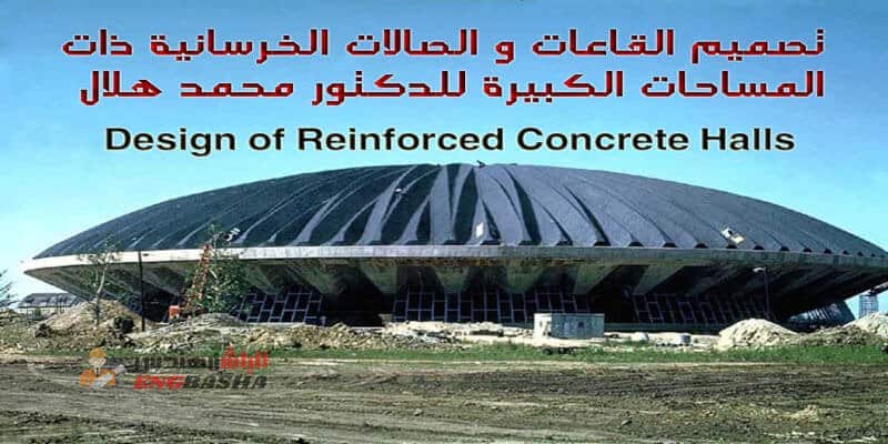
تصميم القاعات و الصالات الخرسانية
Design
of
Reinforced Concrete
Halls
By
DIPL. ING. M. HILAL DR. SC. TECHN.
PROFESSOR, FACULTY OF ENGINEERING
CAIRO UNIVERSITY, GIZA
2005
PREFACE
The contents of this edition are mainly the same as those of the previous one with the necessary corrections and the addition of one of
the biggest structures designed by the author, namely the bulk urea store shown in Fig. VIII-9.
It has further been found more convenient to replace chapter XI on Foundations by a new chapter, published for the first time, on
Folded Plate Structures. A simple sysematic method of design, based on the fundamentals of mechanics and theory of plane structures has
been shown. To illustrate the application of the method, the design and details of three different folded-plate structures worked out by
the author are included in this chapter. The chapter on Foundations is in the author’s textbook on “Fundamentals of Reinforced and Pro-
stressed Concrete”.
The author hopes that this book remains of benefit to structural engineers, graduate and undergraduate students of the engineering faculties and higher institutes in the design of reinforced concrete structures of common use.
March 1978
M. Hilal
Spherical shells (256); Conical shells (260); Edge forces and transition curves (261): Tables of membrane
forces in popular shells of revolution (261): Examples (268) – Circular beams (269).
Cylindrical shells (275): Introduction (275); Membrane theory (276): Beaun theory (288); Analysis of beam act-
ion of symmetrical circular cylindrical shells (290): Examples (296); Analysis of arch action of symmetrical circular cylindrical shells (299): Beternal and inter-
nal forces acting on end diaphragms (309); Construction- al details (311); Examples (312).
Cross-supported cylindrical shell (314); Example (317).
Saw-tooth shells (320); Example (327).
Short shell (328): Examples (331).
Membrane theory of shells of general shape (334):
Basic idea (334); Conditions of equilibrium (337);
Pucher differential equation (340).
Illustrative examples (341): Paraboloid shell of revol-
ution with an equilateral triangular plan (341); Example
(343); Membrane shells with rectangular ground plan (347)
ixamples (351); Conoid shells (359); Escamples (362);
The hyperbolic paraboloid (366); Examples (372).
I-INTRODUCTION
The object of a hall is to cover a limited area that has to be utilised for a certain purpose such as meetings, sports, storage, ex-
hibitions, industry, .. ete.
Reinforced concrete halls and their supporting elements must sa- tisfy the following conditions:
a) The disposition, layout, lighting, ventilation, drainage and in general the architectural composition must satisfy the requirements
of the owner for an economic, efficient and good-looking structure.
b) The structure and its structural members should be so designed and constructed that they are able, with appropriate safety, to witbstand all the loads, superimposed loads and other actions (such as:
differential settlements and temperature changes ) liable to occur during construction and in use.
The object of the design calculations is to guarantee sufficient safety against the structure being rendered ‘unlit’ for service.
A structure is considered to have become unfit! when one or more of its members ceases to perform the function for which it was design-
ed, owing to failure, buckling due to elastic, plastic or dynamic in- stability, excessive cracking, excessive elastic or plastic deformations… etc.
c) The structural supporting elements must be chosen that they give the most economic solution within the available possible means.
a) The initial and maintenance cost must be the minimum possible.
e) The structure should preferably show clearly the statical system adopted and it is generally recommended not to hide the supporting elements. The proportions and dimensions chosen according to a convenient statical system are generally the most convenient and best looking.
The structures dealt with in the following chapters are supposed to be of reinforced concrete. The general principles givea bere cannot be applied directly to prestressed concrete structures without the necessary adaptation.
The object of a hall is to cover a limited area that has to be utilised for a certain purpose such as meetings, sports, storage, ex- hibitions, industry, .. ete.
Reinforced concrete halls and their supporting elements must sa-
tisfy the following conditions:
a) The disposition, layout, lighting, ventilation, drainage and in general the architectural composition must satisfy the requirements
of the owner for an economic, efficient and good-looking structure.
b) The structure and its structural members should be so designed and constructed that they are able, with appropriate safety, to witbstand all the loads, superimposed loads and other actions (such as:
differential settlements and temperature changes ) liable to occur during construction and in use.
The object of the design calculations is to guarantee sufficient safety against the structure being rendered ‘unlit’ for service.
A structure is considered to have become unfit! when one or more of its members ceases to perform the function for which it was design-
ed, owing to failure, buckling due to elastic, plastic or dynamic in- stability, excessive cracking, excessive elastic or plastic deformations… etc.
c) The structural supporting elements must be chosen that they give the most economic solution within the available possible means.
a) The initial and maintenance cost must be the minimum possible.
e) The structure should preferably show clearly the statical system adopted and it is generally recommended not to hide the supporting elements. The proportions and dimensions chosen according to a convenient statical system are generally the most convenient and best looking.
The structures dealt with in the following chapters are supposed to be of reinforced concrete. The general principles givea bere cannot be applied directly to prestressed concrete structures without the necessary adaptation.
تحميل الكتاب
Design of Reinforced Concrete Halls

